
Technical Drawing Requirements for Glass Bottles
Technical Drawing Re
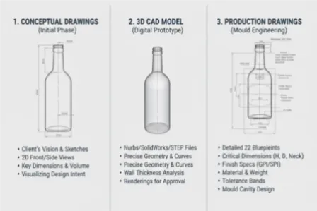
Technical Drawing Requirements – In bespoke glass manufacturing, technical drawings serve as the legal and engineering blueprint for production. To ensure a design is translated accurately from concept to a physical vessel, manufacturers require a specific suite of files that define geometry, capacity, and tolerance.
1. The 2D Technical Drawing
The 2D drawing is the primary reference for quality control and customs documentation. It must be provided in a vector format—typically DWG or DXF—accompanied by a PDF for easy viewing.
- Key Specifications: It must detail the overall height, body diameter, and wall thickness (typically 2.5mm to 5mm).
- Neck Finish: Precise dimensions for the thread type are vital to ensure a leak-proof seal with closures.
- Volume Metrics: The drawing must distinguish between “nominal capacity” (the commercial volume) and “brimful capacity” (the total volume to the rim).
2. The 3D CAD Model
While 2D drawings provide measurements, the 3D CAD model is essential for the engineering of the moulds.
- Mould Engineering: These files are fed directly into CNC machinery to mill the steel or alloy moulds.
- Prototyping: 3D models allow for digital stress testing and volume calculations before any physical glass is melted.
- Visualisation: They enable the creation of high-fidelity renders for marketing and stakeholder approval.
3. Decoration and Artwork Files
If the bottle requires “deep processing”—such as screen printing, acid etching, or heat-transfer decals—vector-based artwork is required.
- Format: Files should be provided in Adobe Illustrator (AI) or EPS format to ensure graphics remain crisp when scaled.
- Placement: The artwork file must include a “key-line” or placement guide relative to the bottle's neck to avoid distortion during application.
4. Technical Specifications Table
Beyond the visual files, a comprehensive data sheet should accompany the submission:
| Specification | Requirement | Impact on Production |
|---|---|---|
| Dimensional Tolerances | e.g. ±0.5mm | Determines the rejection rate during QC. |
| Glass Weight | Grams (g) | Affects shipping costs and perceived luxury. |
| Glass Colour | Flint, Amber, Cobalt, etc. | Dictates furnace scheduling and MOQs. |
| Material Grade | Ordinary, Refined, or High-white | Influences clarity and surface brilliance. |
The Pathway to Production
Once these files are submitted, the project follows a structured manufacturing lifecycle:
- Drawing Confirmation: Finalising blueprints and signing off on tolerances.
- Sample Mould Creation: Building the initial tooling for prototypes.
- Physical Testing: Evaluating samples for thermal shock and pressure resistance.
- Mass Production: Casting the full set of production moulds and commencing the run.
Conclusion
Providing a complete set of 2D and 3D files reduces the risk of costly mould revisions and production delays. For highly complex or asymmetrical designs, it is also advisable to provide physical 3D-printed prototypes alongside digital files to ensure the manufacturer captures every nuance of the design.